Many different models, architectures and standards exist that provide ways to interconnect different hardware and software systems with each other for the purposes of sharing information, coordinating their activities and accomplishing joint or shared tasks.
Computers and networks emerge from the integration of communication devices, storage devices, processing devices, security devices, input devices, output devices, operating systems, software, services, data and people.
Translating the organization’s security needs into safe, reliable and effective network systems needs to start with a simple premise. The purpose of all communications is to exchange information and ideas between people and organizations so that they can get work done.
Those simple goals can be re-expressed in network (and security) terms such as:
- Provide reliable, managed communications between hosts (and users)
- Isolate functions in layers
- Use packets as the basis of communication
- Standardize routing, addressing and control
- Allow layers beyond internetworking to add functionality
- Be vendor-agnostic, scalable and resilient
In the most basic form, a network model has at least two layers:

Upper Layer
The upper layer, also known as the host or application layer, is responsible for managing the integrity of a connection and controlling the session as well as establishing, maintaining and terminating communication sessions between two computers. It is also responsible for transforming data received from the Application Layer into a format that any system can understand. And finally, it allows applications to communicate and determines whether a remote communication partner is available and accessible.
Lower Layer
The lower layer is often referred to as the media or transport layer and is responsible for receiving bits from the physical connection medium and converting them into a frame. Frames are grouped into standardized sizes. Think of frames as a bucket and the bits as water. If the buckets are sized similarly and the water is contained within the buckets, the data can be transported in a controlled manner. Route data is added to the frames of data to create packets. In other words, a destination address is added to the bucket. Once we have the buckets sorted and ready to go, the host layer takes over.
Open Systems Interconnection (OSI) Model
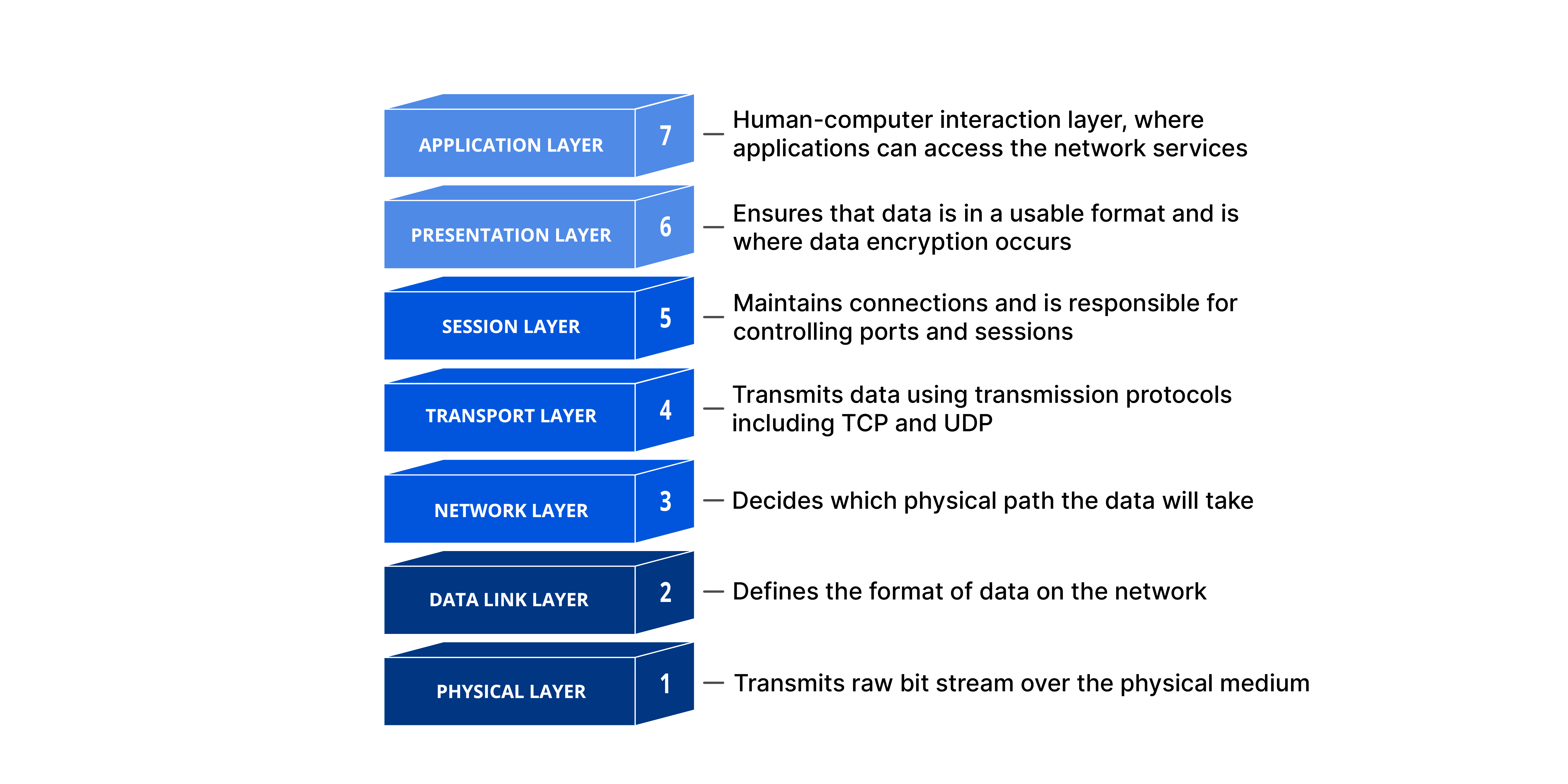
The OSI Model was developed to establish a common way to describe the communication structure for interconnected computer systems. The OSI model serves as an abstract framework, or theoretical model, for how protocols should function in an ideal world, on ideal hardware. Thus, the OSI model has become a common conceptual reference that is used to understand the communication of various hierarchical components from software interfaces to physical hardware.
The OSI model divides networking tasks into seven distinct layers. Each layer is responsible for performing specific tasks or operations with the goal of supporting data exchange (in other words, network communication) between two computers. The layers are interchangeably referenced by name or layer number. For example, Layer 3 is also known as the Network Layer. The layers are ordered specifically to indicate how information flows through the various levels of communication. Each layer communicates directly with the layer above and the layer below it. For example, Layer 3 communicates with both the Data Link (2) and Transport (4) layers.
The Application, Presentation, and Session Layers (5-7) are commonly referred to simply as data. However, each layer has the potential to perform encapsulation. Encapsulation is the addition of header and possibly a footer (trailer) data by a protocol used at that layer of the OSI model. Encapsulation is particularly important when discussing Transport, Network and Data Link layers (2-4), which all generally include some form of header. At the Physical Layer (1), the data unit is converted into binary, i.e., 01010111, and sent across physical wires such as an ethernet cable.
It’s worth mapping some common networking terminology to the OSI Model so you can see the value in the conceptual model.
Consider the following examples:
- When someone references an image file like a JPEG or PNG, we are talking about the Presentation Layer (6).
- When discussing logical ports such as NetBIOS, we are discussing the Session Layer (5).
- When discussing TCP/UDP, we are discussing the Transport Layer (4).
- When discussing routers sending packets, we are discussing the Network Layer (3).
- When discussing switches, bridges or WAPs sending frames, we are discussing the Data Link Layer (2).
Encapsulation occurs as the data moves down the OSI model from Application to Physical. As data is encapsulated at each descending layer, the previous layer’s header, payload and footer are all treated as the next layer’s payload. The data unit size increases as we move down the conceptual model and the contents continue to encapsulate.
The inverse action occurs as data moves up the OSI model layers from Physical to Application. This process is known as de-encapsulation (or decapsulation). The header and footer are used to properly interpret the data payload and are then discarded. As we move up the OSI model, the data unit becomes smaller. The encapsulation/de-encapsulation process is best depicted visually below:

Transmission Control Protocol/Internet Protocol (TCP/IP)
The OSI model wasn’t the first or only attempt to streamline networking protocols or establish a common communications standard. In fact, the most widely used protocol today, TCP/IP, was developed in the early 1970s. The OSI model was not developed until the late 1970s. The TCP/IP protocol stack focuses on the core functions of networking.
| TCP/IP Protocol Architecture Layers | |
| Application Layer | Defines the protocols for the transport layer. |
| Transport Layer | Permits data to move among devices. |
| Internet Layer | Creates/inserts packets. |
| Network Interface Layer | How data moves through the network. |
The most widely used protocol suite is TCP/IP, but it is not just a single protocol; rather, it is a protocol stack comprising dozens of individual protocols. TCP/IP is a platform-independent protocol based on open standards. However, this is both a benefit and a drawback. TCP/IP can be found in just about every available operating system, but it consumes a significant amount of resources and is relatively easy to hack into because it was designed for ease of use rather than for security.
At the Application Layer, TCP/IP protocols include Telnet, File Transfer Protocol (FTP), Simple Mail Transport Protocol (SMTP), and Domain Name Service (DNS).

The two primary Transport Layer protocols of TCP/IP are TCP and UDP. TCP is a full-duplex connection-oriented protocol, whereas UDP is a simplex connectionless protocol. In the Internet Layer, Internet Control Message Protocol (ICMP) is used to determine the health of a network or a specific link. ICMP is utilized by ping, traceroute and other network management tools. The ping utility employs ICMP echo packets and bounces them off remote systems. Thus, you can use ping to determine whether the remote system is online, whether the remote system is responding promptly, whether the intermediary systems are supporting communications, and the level of performance efficiency at which the intermediary systems are communicating.
Internet Protocol (IPv4 and IPv6)
IP is currently deployed and used worldwide in two major versions. IPv4 provides a 32-bit address space, which by the late 1980s was projected to be exhausted. IPv6 was introduced in December 1995 and provides a 128-bit address space along with several other important features.

IP hosts/devices associate an address with a unique logical address. An IPv4 address is expressed as four octets separated by a dot (.), for example, 216.12.146.140. Each octet may have a value between 0 and 255. However, 0 is the network itself (not a device on that network), and 255 is generally reserved for broadcast purposes. Each address is subdivided into two parts: the network number and the host. The network number assigned by an external organization, such as the Internet Corporation for Assigned Names and Numbers (ICANN), represents the organization’s network. The host represents the network interface within the network.
To ease network administration, networks are typically divided into subnets. Because subnets cannot be distinguished with the addressing scheme discussed so far, a separate mechanism, the subnet mask, is used to define the part of the address used for the subnet. The mask is usually converted to decimal notation like 255.255.255.0.
With the ever-increasing number of computers and networked devices, it is clear that IPv4 does not provide enough addresses for our needs. To overcome this shortcoming, IPv4 was sub-divided into public and private address ranges. Public addresses are limited with IPv4, but this issue was addressed in part with private addressing. Private addresses can be shared by anyone, and it is highly likely that everyone on your street is using the same address scheme.
The nature of the addressing scheme established by IPv4 meant that network designers had to start thinking in terms of IP address reuse. IPv4 facilitated this in several ways, such as its creation of the private address groups; this allows every LAN in every SOHO (small office, home office) situation to use addresses such as 192.168.2.xxx for its internal network addresses, without fear that some other system can intercept traffic on their LAN.
Internet Protocol (IPv4 and IPv6)
This table shows the private addresses available for anyone to use:
| Range |
| 10.0.0.0 to 10.255.255.254 |
| 172.16.0.0 to 172.31.255.254 |
| 192.168.0.0 to 192.168.255.254 |
The first octet of 127 is reserved for a computer’s loopback address. Usually, the address 127.0.0.1 is used. The loopback address is used to provide a mechanism for self-diagnosis and troubleshooting at the machine level. This mechanism allows a network administrator to treat a local machine as if it were a remote machine and ping the network interface to establish whether it is operational.
IPv6 is a modernization of IPv4, which addressed a number of weaknesses in the IPv4 environment:
- A much larger address field: IPv6 addresses are 128 bits, which supports 2128 or 340,282,366,920,938,463,463,374,607,431,768,211,456 hosts. This ensures that we will not run out of addresses.
- Improved security: IPsec is an optional part of IPv4 networks, but a mandatory component of IPv6 networks. This will help ensure the integrity and confidentiality of IP packets and allow communicating partners to authenticate with each other.
- Improved quality of service (QoS): This will help services obtain an appropriate share of a network’s bandwidth.
An IPv6 address is shown as 8 groups of four digits. Instead of numeric (0-9) digits like IPv4, IPv6 addresses use the hexadecimal range (0000-ffff) and are separated by colons (:) rather than periods (.). An example IPv6 address is 2001:0db8:0000:0000:0000:ffff:0000:0001. To make it easier for humans to read and type, it can be shortened by removing the leading zeros at the beginning of each field and substituting two colons (::) for the longest consecutive zero fields. All fields must retain at least one digit. After shortening, the example address above is rendered as 2001:db8::ffff:0:1, which is much easier to type. As in IPv4, there are some addresses and ranges that are reserved for special uses:
- ::1 is the local loopback address, used the same as 127.0.0.1 in IPv4.
- The range 2001:db8:: to 2001:db8:ffff:ffff:ffff:ffff:ffff:ffff is reserved for documentation use, just like in the examples above.
- fc00:: to fdff:ffff:ffff:ffff:ffff:ffff:ffff:ffff are addresses reserved for internal network use and are not routable on the internet.